|
Asset Creation Manual
|
   |
   |
Polybump Tool Reference
|
Asset Creation Manual
|
|
|

1. Low Poly File To specify the low poly objects that should receive the date of the high poly object[s] you need to specify the filename (in Alias Wavefront .OBJ format).
2. High Poly Files Specify one or more high poly .OBJs. Using multiple high poly meshes is useful if you had to split your high-res mesh (i.e. a character) into multiple body parts for workflow reasons. Make sure that all of these parts share the same pivot in your 3D application and that they have no transformations applied to them. If needed, use "reset Xform" in 3dsMax or "Freeze all Transformations" in XSI.
3. Activating the "smooth" checkbox will average all vertex normals in the mesh, making the shading appear smooth. When using a mesh exported from 3dsMax, this option is not necessary since smoothing groups will be kept. Applications such as zbrush export meshes with "hard" edges or faceted shading so there it might be useful. However this computation requires some memory and additional Computation time during loading which is not necessary if the object is highly tessellated. By default this option is of and for most high poly meshes this is fine. Only if your High poly has less tessellated areas it might make sense to activate this feature.
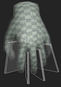
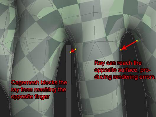
4. Cage file Here you can specify an additional cage mesh to be used during the calculation. Using a cage is advised when you have small folds and gaps in a model, which cause the rays being shot from the low poly mesh to hit the high poly mesh twice or hit an opposing surface in the mesh (see below), creating rendering errors. This can occur for example in the mesh of a hand, in the pits between fingers. Simply adding some boxes between fingers is enough to avoid rendering errors, since they stop the rays from reaching the adjacent finger and thus avoid them hitting the low poly mesh twice.
5. The rayshooting section configures the detail settings of the polybump algorithm.
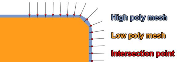
This option defindes the intersection mode for the ray casting algorithm. The algorithm shoots rays with a certain length (see the option below) from the low poly mesh in both directions, outwards and inwards, along the surface's normal. The ray will eventually hit the high poly mesh, and the surface normal at that point will be rendered into the texture as a certain color. If the high poly mesh isn't just one uniform surface, but consisting of several elements (for example a belt around the waist of a character), the ray will hit the high poly mesh at several points. Highest/Latest mode determines which point will ultimately be used for the calculation. Usually, "latest" will deliver best results, as you'll most likely want the top-most parts of the mesh included in the rendering (as in the belt example). It is also the default setting.
This specifies the length of the rays that are being shot. If the rays are too short, they might not reach salient elements of the high poly mesh and produce wrong results, but the longer the ray is, the higher the risk of hitting another point of the high poly mesh becomes, for example in small folds, or in the pits between the fingers. To avoid these problems, a cage mesh can be used (see 4). % of low poly size means the following: A bounding sphere is created around the low poly mesh, fully encapsulating it. The radius of this sphere determines the ray length: 10% means the ray length is 10% of the bounding sphere diameter.


“use nearest hit” with 2%, 5% and 50%


“use latest hit” with 2%, 5% and 50% Note how very short rays don't reach the high poly mesh and produce black spots on the normal map (left pictures). Also note how using nearest hit instead of latest hit doesn't render the top-most surface elements of the high poly mesh (belts, clips, etc.)
If you activate this option, polybump will calculate a horizon map which can be used as source for various outputs (e.g. accessibility map, Unoccluded area direction, possible future use: spherical harmonics) The horizon map is essentially the ambient occlusion of the high-poly mesh projected onto the low-poly mesh and baked into a texture. You can set it to either low, med or high to define the quality. The higher the quality, the longer the calculation will take. This quality setting has the most significant impact on calculation time, so low quality should be used for testing and troubleshooting, and high only for final renders. Setting the option to "none" means that no horizon map will be rendered. Note that the ray length parameter also influences the horizon map rendering. Using short rays will produce a more high-contrast occlusion map, with darkening visible in rather tight folds only, while using long rays will produce a very "soft" shading where even slight pits in the surface will become darker. However, using a very high ray length also means increasing rendering time.
Enabling anti-aliasing will improve the texture quality, but will also increase calculation times. Full anti-aliasing produces better quality than selective anti-aliasing, but it also requires longer calculation times.
6. Output Specifies the texture dimensions.
7. Preview This section lets you preview the objects you chose for computation. The low-poly mesh will be rendered in white, and the high-poly mesh in black. If there is a cage mesh present, it will be rendered in red. You should use this view to check if the objects align properly and share the same position, this is especially important when you use OBJs exported from Zbrush or XSI. If everything is correct you should see the objects overlapping each other like here:


The available options are:

0 (no change) means a 1:1 ratio, the final texture will be as big as you originally specified in polybump. 1 means a smaller texture, -1 means a larger texture, and so on.

You can choose between no expansion, 1,4,8, and 16 pixels.


No expansion 16 pixel expansion
There are many possibilities how to compute tangent space matrices per vertex and that computation is required to reconstruct the normals in the shader when rendering the low poly model. To avoid distortions the same computation should be used when transforming the world space normals to the tangent space (exporting .srf). Reference:
|
Triangle Mesh Tangent Space Calculation |
|
Martin Mittring,  ShaderX4, 2006 ShaderX4, 2006 |
High quality normals in object/worldspace still exists in the .srf file and can be extracted and possibly transformed from there into some other space.
If you check the unoccluded area direction (_DDNDIFF) option, polybump will create a _DDNDIFF.TIF file containing the normal map with the horizon map baked in. This will have a similar effect as an ordinary normal map combined with an ACC map in the diffuse slot, however it encodes the opening angle of the unoccluded cone and that allows to express some sort of soft shadows of the high poly details. The ambient occlusion will react to light influence more properly and ambient occlusion will disappear where it is directly lit. Simply baking ambient occlusion into the diffuse texture can look like dirt as even lit directly the darkening remains. _DDNDIF requires quite a lot of additional texture memory (_DDN is still required) and it should be carefully considered if this feature is needed.
If a _DDNDIFF texture is present in the directory of the material and the other textures, and you have specified an ordinary _DDN texture in your material's normal map slot, CryENGINE®2 will automatically choose the _DDNDIFF texture for the advanced rendering technique, provided the textures have the same prefix (as in: boots_DDN.tif and boots_DDNDIFF.tif).

Example 1 : Low poly mesh with non-chamfered edge, separate smoothing groups. Normals are perpendicular to the polygon on the entire surface. Edge detail gets captured (see intersection points), but only if the edge of the low poly mesh touches the high poly mesh where the bevel occurs. Even then, the rounded bevel isn't accurately represented due to the sudden change of the normal orientation (see the sharp edge in the texture):


Example 2 : Low poly mesh with non-chamfered edge, separate smoothing groups. Edge detail in the "deadzone" doesn't get captured because the low poly mesh is too far away from the high poly mesh. Note how the edge/corner appears almost 100% sharp in the render view:


Generally, sharp edges produce poor results, especially when the low poly isn't positioned so the corner of the low poly directly touches the high poly mesh.

Example 3 : Low poly mesh with non-chamfered edge, unified smoothing groups. Normals are averaged across the surface, they are gradually interpolated from perpendicular to the surface (upper left) to 45 degrees at the corner. The result is a gradient in the normal map, and the rounded edge is represented accurately. Using this method is sufficient for representing rounded edges and even corners, however it fails if the final mesh is viewed at an extreme angle (see bottom picture).


Example 4 : 1-segment chamfer, unified smoothing groups (or smooth edges). The normals remain perpendicular to the surface until shortly before the bevel, which results in a softer gradient in the normal map, and the rays hit the high poly mesh at a less acute angle than with the method above (compare the diagrams), which results in less vivid colors in the normal map. The final result is slightly better compared to not chamfering the edges, however the most significant improvement can be seen when looking at it from an extreme angle (see bottom picture).


Low poly meshes with their corresponding normal maps in 3dsMax: No chamfer - left, two-segment chamfer - right.
In conclusion, it is advisable to use low poly meshes with unified smoothing groups, and to additionally chamfer edges and corners if they can be seen at extreme angles. However, it is not always necessary to chamfer the low poly mesh, and using very simple meshes can produce surprisingly good results if they are carefully matched to the high-poly mesh.