Breakable Objects
Breakable objects consist of separate pieces which are held together by joints.
The single parts can be separately disjointed, by applying physical force (bullets, player interaction, explosions) bigger than the joint limits.
In general, Breakable objects are placed in Sandbox as brushes
A perfect example for a breakable objects would be a road sign, a wooden fence, or a wooden shag.
Table of Content
Sample File
Sample File:
 breakable_example.max
General Setup in 3d applications
* The objects must have several nodes in max, each with its own physics.
- Nodes are held together with joints (each joint can connect only 2 parts).
- Naming convention for Joints: $joint01, $joint02,...
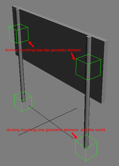
- Joints are represented in the 3d application with helper objects (dummies, Nulls..). They need to intersect with the physics proxy (!) of 1 or max. two geometry objects.
- The Z-orientation of the joint pivot should normally point upward (see Debug section)
- Alternatively, one can explicitly specify part names in the joint name using this format: $joint1_part1_part2. This can be useful at complicated junctions where geometrical intersections can find more than 2 parts
- When a joint object intersects only with one node, a joint between the object and the world is created.
- The size of the dummy object does not have any effect on the strength.
- It is, however, used to re-attach joints to broken parts if some geometries also have procedural breaking on (namely: when a part breaks procedurally, all joints that are attached to it are checked for intersections with the newly formed pieces, and are re-attached to them if needed)
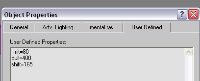
- The strength of the joints and the mass of the separate are defined in the node properties (different name in every 3d application; in 3ds: objects Properties)
- Specific joint limits are relative to the joint's normal, represented by the helper node's z axis. For joints that specify part names explicitly, care must be taken that the normal points into the 1st parts (otherwise push and pull limits will switch meanings)
- Turn OFF "Merge All Nodes" on export
- Objects can be placed as brush or geom. Entity
- example for dummy placement
- Example for joint properties
Each time an external force (from collisions with other objects, or bullet hits) is applied to the object, the system calculates internal forces needed to hold the object parts together, and if some forces breach the threshold, the corresponding joints are removed. Then part connectivities via remaining joints are recomputed and isolated islands are moved to new entities.
Node Properties
The nodes need properties attached (depending on software) to work correctly in the engine.
entity (render geometry property)
If the render geometry properties include "entity", the object will not fade out after being disconnected from the main object.
box (render geometry property)
If the render geometry properties include "box", the engine will use a simple box (based on the bounding box of the object's physics proxy) as the collision geometry. This helps speeding up physics calculation.
mass=VALUE (render geometry property)
Mass defines the weight of an object based on real world physics
mass=0 sets the object to "unmovable". This is used on the basement of a house for example or the sign pole which should not be movable and always stay in the original position. When used in brushes and Geom Entities, this is the final part's mass. When used in regular Entities, all parts masses are scaled so that their total mass gives the mass specified in the entity properties. CAUTION! You must either define this value or density to ensure the simulation is working correctly.
density=VALUE The engine automatically calculates the mass for an object based on the density and the bounding box of an object. Can be used alternatively to mass.
limit=VALUE (Joint object property)
limit is a general value for several different kind of forces applied to the joint. It contains a combination of the values below.
CAUTION! This value needs to be defined, otherwise the simulation will not work correctly. Crysis Example values: 100 - 500 can be broken by a bullet; 10000 can be broken by the impact of a driving vehicle or a big explosion.
The following values are optional and are used to fine tune the "limit" settings.
bend=VALUE (Joint object property)
maximum torque around an axis perpendicular to the normal.
twist=VALUE (Joint object property)
maximum torque around the normal
pull=VALUE (Joint object property)
maximum force applied to the joint’s 1st object against the joint normal (the parts are "pulled together" as a reaction to external forces pulling them apart)
push=VALUE (Joint object property)
maximum force applied to the joint's 1st object (i.e. the one whose name is listed first in the joint's name, or if the names were not specified, the object the joint's z axis points towards) along the joint normal; joint normal is the joint's z axis, so for this value to actually be "push apart" (as a reaction to external forces pressing the parts together), this axis must be directed inside the 1st object
shift=VALUE (Joint object property)
maximum force in the direction perpendicular to normal
Dissolving into particles\pieces
Jointed Objects can be set up to break in smaller pieces when being detached from the joint. i.e. a wooden sheet breaks into several planks. The object properties must contain the information about the pieces used. i.e. "pieces=$blah1", "pieces=$rock1". Several objects can share the same name, but it is also possible to set up the pieces with different names, i.e. "pieces=$blah1,$blah2". Pieces need to be linked to the object they should replace later on.
Level of detail settings
LODs per object can easily be added by naming them $lod1; $lod2, $lod3... and linking them to the relevant subobjects. In order to make differentiation easier, a postfix can be added; i.e. "$lod1_wooden plank"
Occlusion Proxy
An
Occlusion Proxy can be added by naming it $occlusion and linking it to the relevant jointed object; like a big sheet of metal on a metal fence or a wooden wall on a hut. Occlusion proxy is allowed to have open edges and need to be as low as possible (something around 2-10 polys).
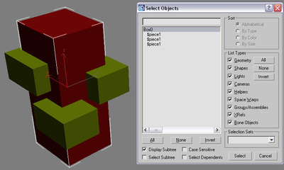
Instancing within breakable objects
Instancing objects is used to optimize render time by reducing drawcalls and memory consumption. The engine automatically detects identical geometry elements within the exported objects.
There is no special setup needed to take advantage of this feature. UVs and relative point position to the pivot need to be identical in objects in order to qualify them for instancing.
Linking Objects to simplify export
Linked objects don t need to be exported, just the Root node needs to be added to the exporter list. All child nodes will automatically be exported. The name and pivot will be derived from the root joint.
- Example of linking objects and joints for simpler export
Setup in Sandbox
Add the object as a brush or a Geom. Entity. In case of a brush, the engine will detext automatically that the object is breakable. For multiplayer where breaking objects has a massive impact on the data transfer, breakability is automatically disabled (might change later)
Debugging
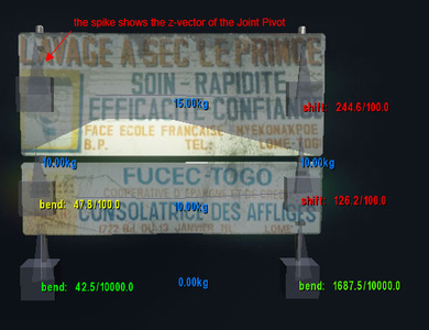
* p_debug_joints 1 shows the default debug mode for joints (see picture below); p_draw_helpers needs to be activated
- CAUTION Never scale a joint! If you need a new size, create a new joint. the scaling value will be passed on to the engine and causes wrong results in the simulation.
- The "spikes" on the joint objects show the orientation. For consistent results, they should point into the z-Axis (up). (see picture below)
- The blue colored numbers show the mass of the single pieces. Note the "0.00kg" this is the mass of the top node - in this case a dummy.
- Joints linked to the world are displayed red.
- When a force is applied to a joint, the direction is shown (in this case shift and bend), together with the strength and the limit of the particular joint. Green text represents an impact with an impulse much lower then the joint limit. Yellow represents values closer to the joint limit. Red represents values which were higher than the limit - in this case the joint is broken.
- NOTE: the debug mode is handy to see how the impulse of weapons react with the breakable object. set the general limit first and then fine tune the specific limits by setting them explicitly for shift, bend...