Character Creation Tutorial
Orientation

To follow along with this tutorial, you should have the files shown above. They are available freely online, and are also located in the \Objects\characters\human_male folder of the SDK.
Character assets for CryENGINE®2 are stored in three max files, a file with the character’s name, a file with the character’s name and a _LOD1 suffix, and a head with an arbitrary name. You can see character.max and character_LOD1.max to the left.
For the most part, CHR is the CryENGINE®2 character file format, there is also CGA , which will be mentioned later.
Special Note: Throughout this tutorial I will talk about using the SDK example files but also list extensive notes, for those of you who will be rolling your own characters from scratch.
3dsMax Exporter Setup

Plugin
There are a few different ‘flavors’ of the exporter, depending on which version of max you use. Shown at left are the versions compiled as of Nov 2007. The CryExport plugin should be placed in the ‘ plugins ’ folder located in your 3dsMax root directory.
INI File In addition to the plugin, you need to place a text file called ‘ CryExport.ini ’ in the same folder (/plugins ), the text file should have paths to the CBA file and the Editor application.
[Sandbox] path J:\Game02 \bin32\Editor.exe= animlistpath J:\Game02 \Game\Animations\Animations.cba= buildPath J:\depot \SDK\CryENGINE2\Main\=
The characters marked in blue are parts of the path that you would change to reflect locations on your hard disk.
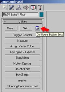
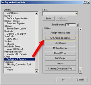
Adding the CryExport Utility
Under the Utility panel, go to ‘ Configure Button Sets ’, scroll down to Crytek, and drag the ‘ CryENGINE® 2 Exporter ’ over to a utility button.
Special Note:
The Resource Compiler folder is derived from the Editor path, you should have a resource compiler in the /rc folder. If you do not have a Resource Compiler, make sure you have the SDK installed properly.
File Layout: character.max (LOD0/2/3)
I will briefly explain the nodes you see in this max file. There are
render meshes ,
thin/fat variation meshes , a
live deforming skeleton , and a
live phys skeleton .
Render Meshes:
- These are the mapped character geometry that you see in the game.
- Vertex Colors on the LOD0 ($character) mesh denote masked areas that can be morphed between thin and fat once in the engine.
- The levels of detail or LODs are meshes with lower polygonal resolution that automatically fade in based on your distance from the character. (in the game world)
- The material on this mesh should correspond with an MTL file in the character’s folder
- sdk_character.mtl in the example files
- Render Mesh Nodes:
- $character
- $character_LOD2
- $character_LOD3
Thin/Fat Variation Meshes:
- These are two variations of the LOD0 mesh ($character)
- Because they are morphs, they must retain the LOD0 point index
- Thin/Fat Variation Mesh Nodes:
- $character_thin
- $character_fat
Live Deforming Skeleton:
- This is the skeleton that deforms the render meshes
- The bone geometry of this skeleton is used for hit detection and physics in the live character (non-ragdoll)
- The materials applied to this skeleton are used for hit detection, to tell the engine what part of the character you have hit.
- There are ‘attachment nodes’ in this hierarchy
- Example: $weapon_bone, this is where the weapon will be attached in the engine.
- This a basic ‘Biped Skeleton’ but other than ‘attachment nodes’ there are some additional nodes used for automatic foot plant and gait detection
- $’Bip01 L Heel’ and $‘Bip01 L Toe0Nub’ on the left foot. (also present on the right foot)
- Live Deforming Skeleton Nodes:
- Hierarchy of nodes under and including $Bip01
Live Phys Skeleton:
- Think of this skeleton as a set of switches, a node being present in this skeleton signifies that it’s counterpart in the live deforming skeleton is physicalized in the engine while the character is alive .
- Each node in this skeleton also stores physical properties for it’s corresponding bone in the deforming hierarchy, this is stored in the phys bone’s IK properties.
- Live Phys Skeleton Nodes:
- Hierarchy of nodes under and including $’Bip01 Pelvis Phys’
File Layout: character_LOD1.max (LOD1)
I will briefly explain the nodes you see in this max file. There are
render meshes ,
thin/fat variation meshes , a
ragdoll deforming skeleton , and a
ragdoll phys skeleton .
Render Meshes:
- This is the mapped character geometry that you see in the game.
- Render Mesh Nodes:
Thin/Fat Variation Meshes:
- These are two variations of the LOD1 mesh ($character_LOD1)
- Because they are morphs, they must retain the LOD1 point index
- Thin/Fat Variation Mesh Nodes:
- $character_thin_LOD1
- $character_fat_LOD1
Ragdoll Deforming Skeleton:
- This skeleton hierarchy must match the hierarchy of the LOD0 skeleton exactly (character.max deforming skeleton)
- The bone geometry of this skeleton is used for the ragdoll physics
- This geometry should consist of spheres, boxes and capsules
- Arbitrary geometry is supported, but could slow perfromance
- The materials applied to this skeleton are used for hit detection, to tell the engine what part of the character you have hit.
- Ragdoll Deforming Skeleton Nodes:
- Hierarchy of nodes under and including $Bip01
Ragdoll Phys Skeleton:
- As with the LOD0, think of this skeleton as a set of switches, a node being present in this skeleton signifies that it’s counterpart in the ragdoll deforming skeleton is physicalized in the engine, while the character is in a ragdoll state.
- Each node in this skeleton also stores physical properties for it’s corresponding bone in the deforming hierarchy, this is stored in the phys bone’s IK properties.
- Ragdoll Phys Skeleton Nodes:
- Hierarchy of nodes under and including $’Bip01 Pelvis Phys’
File Layout: head.max
I will briefly explain the nodes you see in this max file. There are
render meshes ,
morph targets ,
thin/fat variation meshes , a
deforming skeleton .
Render Meshes:
- This is the mapped character geometry that you see in the game.
- Render Mesh Nodes:
Morph Targets:
- These are the ‘morph targets’ or ‘blend shapes’ that drive the facial deformation of the render mesh
- Morph Target Nodes:
- $ Brow_lowerer
- $ Jaw_dropper_01
- $ Jaw_pusher
Thin/Fat Variation Meshes:
- These are two variations of the LOD0 mesh ($head)
- Because they are morphs, they must retain the LOD0 point index
- Thin/Fat Variation Mesh Nodes:
Deforming Skeleton:
- This skeleton hierarchy must not have more members than the deforming skeleton of the character you will attach the head onto (character.max)
- The skeletons do not have to match, but this SLAVE skeleton, must have less bones than the MASTER skeleton, more on this later.
- Arbitrary geometry is supported, but could slow performance
- Deforming Skeleton Nodes:
- Hierarchy of nodes under and including $Bip01
The Render Mesh
Enough with all the explanations, let’s dig in. It’s also time for some pictures.
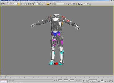
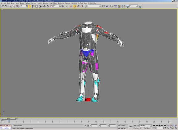
Load character.max , this is what it should look like when loaded. These are the render meshes , you are currently viewing all three (LOD0/2/3)
Things to keep in mind when creating the render mesh of a character:
- It’s pivot should be at 0,0,0
- The character must be facing down the positive Y axis
- It should have no transformations applied to it (pos, rot, scale)
- If so, apply a reset xform before you start
- Make sure the model matches the joints in the skeleton
- The live deforming skeleton should be in it’s ‘bind pose’ when you apply the Skin modifier
Special Note:
When creating your own character, you do not need to match your render mesh to our SDK skeleton. But keep in mind that this means your character cannot use the existing Crysis animation set. If you do want to use a custom character/skel, please look into how difficult it is to create all the animations needed to get a custom skeleton moving around with decent motion fidelity in a next-gen game, it can be hundreds or thousands of animation assets.
Model your character to fit this skeleton, then use Skin (or Physique if you’re a masochist) to weight your render meshes to the deforming skeleton .
‘Deforming’ and ‘Phys’ Skeletons
Character assets are broken up into a main character file (character.max) and an LOD1 file (character_LOD1.max), each file has a deforming and phys skeleton. It is critical to understand the role of each skeleton in each file.
The live deforming and live phys skeleton in the main file (LOD0/2/3) store the hit detection and physics properties for the live skeleton , while the ones in the LOD1 max file store the hit detection and phys properties for the ragdoll .
Not to beat you over the head, but this is important:
Main Character File (character.max)
Character Render Mesh weighted to Live Deforming Skeleton whose physical properties are stored in the Live Phys Skeleton
LOD1 Character File (character_LOD1.max)
Character Render Mesh weighted to Ragdoll Deforming Skeleton whose physical properties are stored in the Ragdoll Phys Skeleton

Open the Layer Manager, and you will see that there is a layer called ‘ bip ’ that is hidden, hide ‘ default ’ and unhide ‘ bip ’, you will then see this:
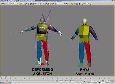
These are the live deforming and live phys skeleton of the LOD0/2/3 file (character.max)
The ‘Deforming’ Skeletons
In case you skipped the file layout section, here is what the
deforming skeleton is responsible for:
- This is the skeleton that deforms the render meshes
- The bone geometry of this skeleton is used for hit detection and physics in the live character (non-ragdoll)
- The materials applied to this skeleton are used for hit detection, to tell the engine what part of the character you have hit.
- There are ‘attachment nodes’ in this hierarchy
- Example: $weapon_bone, this is where the weapon will be attached in the engine.
- This a basic ‘Biped Skeleton’ but other than ‘attachment nodes’ there are some additional nodes used for automatic foot plant and gait detection
- $’Bip01 L Heel’ and $‘Bip01 L Toe0Nub’ on the left foot. (also present on the right foot)
- Deforming Skeleton Nodes:
- Hierarchy of nodes under and including $Bip01
- The Ragdoll Deforming Skeleton , located in the LOD1 asset file, is used for collision and hit detection in the ragdoll.
Special Note: The recommended number of physicalized bones in a humanoid biped ragdoll is 10-14

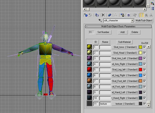
The deforming skeleton 3dsMax material setup for a Crysis humanoid character.
Material Setup As you can see, the deforming skeleton has different submaterials assigned to it, these are used for hit detection in the engine. On Crysis, the first 10 submaterials were devoted to hit locations, and any after that were used for textures. This can vary by project.
The submaterials in the engine correspond to surface types defined by code
If you open the sdk_character.mtl in the CryENGINE®2 Material Editor, you will see that the submaterials used for hit detection are assigned to corresponding surface types ; they are also assigned the ‘ nodraw ’ shader.
Special Note: Here are some things to keep in mind when altering or replacing the deforming skeleton with something of your own:
- Keep your bones and rig elements in the ‘bip’ layer
- Allows animators to easily hide the rig
- Allows cryTools to manage rig visibility automatically
- If you are using a new or custom skeleton, you should be prepared to recreate the full locomotion animation set to support it’s moving in the game.
- The skeleton must face down the +Y axis
- Nodes in the hierarchy should have no scale applied to them
- All bones/nodes should have 100% XYZ scale
- There is a bug in Max where mirroring bones causes them to have a -100% scale: be on the lookout for this. Use the mirror function in ‘Bone Tools’ before converting them to ePoly.
- The root bone pivot should be placed at 0,0,Z in world coordinate space.
- The pivot of the root bone must have its positive X looking forward, positive Y looking left (of the facing direction of the character) and positive Z looking up vertically.
- No bones can be outside of the skeletal hierarchy, the exporter starts at one root bone and steps through all its children.
- This also means no external bones can be constrained into the skeleton
- If you want bones to act like they are outside of the skeleton, you can change their transform inheritance in Command Panel->Hierarchy->Link Info->Inherit
- Once they are not inheriting transforms from their parents, you can drive them with constraints as if they were outside the hierarchy
- The bones of the spine and head need to match the orientations and names of the biped skeleton for lookIK to work
- The names are 'Bip01 Head' 'Bip01 Neck' 'Bip01 Spine3' 'Bip01 Spine2'
- If you want to have rig elements inside the hierarchy, keep them to the periphery and use the prefix '_' to comment them out of export
- The '_' prefix effectively comments an object, and all of it's children out on export
- If you must have them in the hierarchy, and they are exported into the engine, try not to have them be splines or shapes, convert them to polygons
- Keep in mind that any rig elements inside the hierarchy that are exported will be null bones in the engine, and take up memory/cpu time, so do this sparingly
- It’s a good idea to put your hit material submats first for humanoid skeletons that you will re-use, this way the numbers will not change based on how many different texture submats you use.
Ragdoll Deforming Skeleton (LOD1)
Above you see the ragdoll deforming skeleton and ragdoll phys skeleton from the LOD1 file.
The deforming skeleton in the LOD1 asset file is used for collision/hit detection in the ragdoll, this is called the ragdoll deforming mesh . It can be made from arbitrary geometry, like the live deforming skeleton , but should be made from capsules, boxes, and spheres.
Special Note: Biped can be finicky, the best way to create your own custom ragdoll deforming skeleton is to align capsules and boxes to your existing skel, then via editPoly, attach them to your node and delete the old geometry.
The ‘Phys’ Skeletons
There are two
phys skeletons that a character has, one in the main character file, and one in the LOD1. In case you skipped the file layout section, here is what the
phys skeleton is responsible for:
- Think of this skeleton as a set of switches, a node being present in this skeleton signifies that it’s counterpart in the deforming skeleton is physicalized in the engine.
- Each node in this skeleton also stores physical properties for it’s corresponding bone in the deforming hierarchy, this is stored in the phys bone’s IK properties.
- Phys Skeleton Nodes:
- Hierarchy of nodes under and including $’Bip01 Pelvis Phys’
The ragdoll phys skeleton is stored in the LOD1 file ( character_LOD1.max ). It stores the ragdoll physical properties of the character in the same way that the live phys skeleton stores them for the live deforming skeleton .

Here we are looking at the phys skeleton in the main character file ( character.max ), this is also known as the live phys skeleton , because it is used for the live character physics.
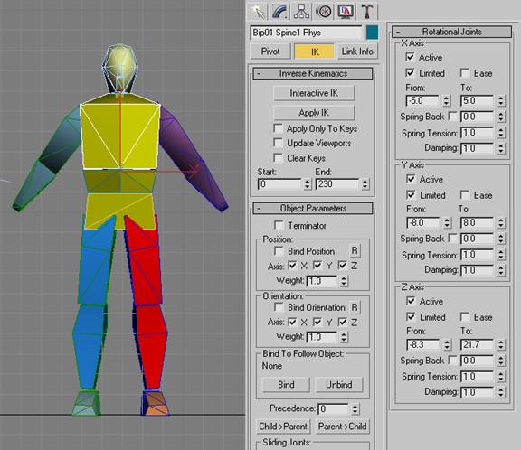
Each part of the phys skeleton references a node in the deforming skeleton , it has the same name as that node, but the suffix ‘ phys ’. In the example above you see ‘ Bip01 Spine1 Phys ’, which is the phys node referring to ‘ Bip01 Spine1 ’ in the deforming skeleton .
Limits The phys skeleton nodes match the orientations of their counterparts in the deforming mesh exactly, and their IK limits are the offset rotations that that physics will be able to deviate from any playing animation. Be sure to check ‘ Active ’ and ‘ Limit ’, then enter in your values. If your limits exceed +/- 90 degrees read on about ‘ ParentFrames ’.
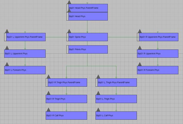
ParentFrames When the needed rotational limits of a node in the phys skeleton exceed +/- 90 degrees, you will often need to use a ‘ ParentFrame ’. A ParentFrame is a node that sits above the phys node and zero’s out it’s rotations. It is basically an identical copy of the node, which sits above it in the hierarchy, and has the suffix ‘ parentFrame ’. Here is an example of a phys hierarchy with parentframes on all limbs:

Dampening and Spring Tension Stiffness of an angular spring at a joint can be adjusted via "Spring Tension" parameter. A value of 1 means acceleration of 1 radian/second2 (1 radian = 57°). Damping should also be set to some reasonable value (1.0 corresponds to fully dumped oscillations for an isolated joint, 1.0 is the recommended value ).
As shown above, each piece of the phys skeleton has properties under the Hierarchy tab( IK ).
Special Notes:
- If you have a node present in the phys skeleton, it must have physical properties
- If all it’s limits are defaulted to ‘0’ it will not be export into the game engine
- This is important with the root, which should have no real limits, but needs garbage numbers in the limit fields to export properly (check SDK char)
- The recommended number of physicalized bones in a humanoid biped ragdoll is 10-14
- The deforming skeletons will have their shapes and mass taken into account, so the mesh must be physically valid in order to behave convincingly
- Heavy-light-heavy patterns in bone structure should be avoided in the 'Phys Skeleton’.
- A typical example from biped is spine-neck-clavicle-upper arm connection with heavy spine, light neck and clavicle, and relatively heavy upper arm.
- For ragdoll phys skeletons it's recommended to exclude neck (not necessarily neck1,2, though) and the clavicles from the Phys Skeleton.
- Try to have your ragdoll deforming skeleton consist of primitives wherever possible.
- Try to avoid sharp corners near joints
- Avoid using joints with all 3 axis locked whenever possible, because they slow down the simulation w/o doing anything useful
- Remember: Keep the phys mesh pivot points alligned in orientation to the bones they are suppose to be physicalising. When the phys IK values are set, they are translated onto the bones of the character in the game. But those IK values work with the pivot alignment. If the bone pivot orientation is different from that on the phys mesh, when in the game, the bone will be rotated to align to the phys mesh, thus creating the undesirebale effect.
- When creating your own phys skeleton, because it needs to have the same orientations as the deforming skeleton, just snapshot your existing skeleton. Then, remove parts you do not want, reparent the children, and rename them. When you have removed one of these, it will remain locked in default orientation, and will not be physicalized. Check the spine setup on the SDK character for an example.
- You can also place certain words in an object’s ‘user defined properties’ to force it into a primitive in the engine, this will generate a bounding primitive around the mesh. Here are some you can try
- nonphysical
- sphere
- box
- capsule
- cylinder
- If your limits and deforming skeleton meshes match for ragdoll and live skeletons, you can store all the rendermeshes in one file, this makes things a lot simpler
- You no longer have two files to manage and two hierarchies to sync
Advanced Setup
These are some techniques/features that are not present in the SDK character example.
Character Ropes
Characters with ropes and hinges are not included in the SDK, but I will touch on them quickly.

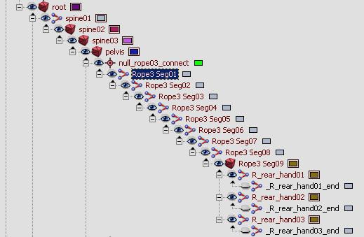
Here is a piece of the ‘Trooper’ hierarchy, Rope3 is a physicalized rope
Character Ropes
- In order to have some character bones simulated using rope physics one has to name the corresponding bones ' ropename[space]ropesegmentname '. ropename can be any name starting with ' rope ' (internally all bones that share one rope name are united into one rope), and rope segment can be any text (internally it is discarded, it should be used just to avoid naming collisions among bones that belong to one rope).
- All segments in one rope should have approximately equal length. Note that a rope bone should never be the leaf bone (w/o children), since the bone after the last rope bone is used to provide terminal rope vertex. Also note that currently ropes cannot connect 2 physicalized parts of a skeleton; they can be either "roots" (ex: hanging light cord), or leaves (ex: character's ponytail or braid).
- In game script one should first create some physical entity, then load and physicalize the character model. By default all bones are physicalized (unless " Phys" counterpart skeleton is present, which will most likely be the case only for characters). Note, however, that rope bones normally should not be a part of main character physics (which for hanging lamp will most likely be a rigid body), thus they should have 'nonphysical' keyword in their user-defined properties (as well as other bones that do not represent physical geometry).
- During the physicalization ropes are created and stored internally in the character system. The 1st end of the rope is the one that is closer to the root bone. Both the 1st and the 2nd ends are automatically tied to character physical entity if they are connected to its physicalized parts (not necessarily directly).
- In order to alter parameters of rope physics one should call:
- SetCharacterPhysics(slot_number,"ropename", PHYSICSPARAM_ROPE,param_table).
- param_table can contain the following fields:
- length - full length of the rope;
- entity_id_1 - entity id the 1st rope end is tied to (-1 if statically tied world, -2 if not tied at all);
- entity_part_id_1 - entity part id the 1st rope end is tied to
- end1 (vector) - the 1st end attachment point (if unspecified, it is assumed to be current end point position);
- end2 (vector) - the 2nd end attachment point;
- check_collisions - 1 if the rope should collide with the environment (0 otherwise);
- coll_dist - rope thickness for collision detection.
- Currently ropes cannot apply forces or otherwise alter the behavior of the objects they are colliding with, save the objects they are directly tied to (and tied objects receive impulses only when the rope is fully strained along a straight line).
- 'Stiff' ropes can be mimicked by having few rope segments (bones) and setting up mesh skinning so that visually the rope bends smoothly rather than abruptly at joint points.
Adjusting Rope Properties There are rope properties that can be set in 3ds max. These properties are stored in the first link and effect the entire chain.
To enable these you should add the word ‘ physical ’ to the ‘ User Defined Properties ’ of the first bone in the rope chain.
The following settings refer to the rollout in Hierarchy -> IK -> Rotational Joints
- character collision – y axis active, will collide with the local character
- environment collision – x axis active, will collide with the environment
- joint limit – spring tension x, this will be the per-bone rotational limit for the chain
- stiffness – maximum x limit
- stiffness decay – maximum y limit
- damping – maximum z limit
Character Hinge Attachments
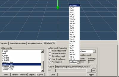
When adding CGF bone attachments in character editor, you can create hinge joints to give the rigid attachments realistic secondary motion. Just select the bone attachment, then check ‘
Physicalized ’, select a hinge rotational axis, and specify some values. It takes some trial and error to get right, but the results are great.
CGA Files
A CGA file is a conglomerate of CGF objects and animation data. They are used for rigid, non-deforming animations, like the baked physics above. CGA files are like character files with some major differences:
- They store a hierarchy but no skinning data
- There are CGF files attached to this skeleton, which are also stored in this file
- There is a default animation also stored in the mail file
- It is referenced as ‘Default’
- A CGA can also play ANM files, and reference them in a CAL file.
- CGA animated objects must use TCB controllers in 3dsMax; to reduce size, reduce keys
Special Notes: To convert many objects to TCB you can use this snippet of maxscript (or cryAnimationTools)
for%BLACK%objin%BLACK%selectiondo %BLACK%( %BLACK% obj.rotation.controller tcb_rotation ()= %BLACK% obj.position.controller tcb_position ()= %BLACK%)
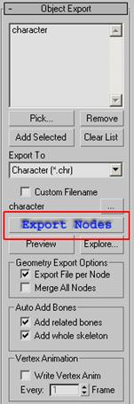
Exporting Your Character into CryEngine2
Add your render meshes into the ‘
Object Export ’ listbox, make sure that ‘
Export To ’ is set to ‘
Character (.chr) ’ and then click ‘
Export Nodes ’. Your CHR should be saved to disk in the location of the max file, you can click ‘
Exlore… ’ to go there immediately.
Special Notes: You can export multiple meshes at once; just add them in the Object Export list box.
CAL files
In the SDK folder (/human male), you may have noticed a CAL file, this is a
Character Animation List . It points the engine to the animations a character can playback.
Special Note: Every character must have a CAL file, if you created a custom skeleton you might have to make custom anims to drive it, to do this you need to make a custom CAL file and Animation graph, which is beyond the scope of this tutorial.
CDF files
A CDF or ‘
Character Definition File ’ is used to group many CHR files together, or CHR files that have CGF attachments. For more information on assembling characters in the engine, please refer to the Character Editor documentation.
Special Note: You can also attach ‘null sockets’, which can be placeholders for particle effects, or node orientations for things like grabbing or orienting an object onto another in game.
In Engine Debugging (Animation, Hit Detection, Physics)
It can be difficult to tell if your skeletal changes are working in the engine. Well, it’s easy to see if it’s deforming by simply playing an animation on it. The difficult thing can be checking the phys setup. Here’s how:
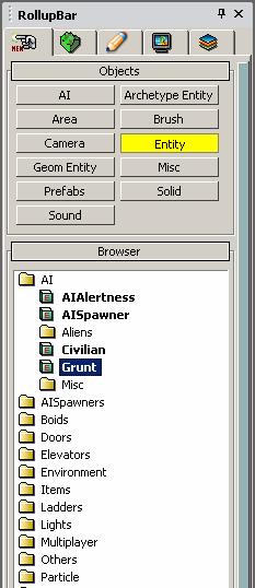

On the Rollup Bar , select Entity , then drag a Grunt into an empty level. Under the ‘ Entity Properties ’ for the Grunt, find the ‘ Model ’ property. When you reload the entity, you should now see something like this:
‘Grunt’ Entity in engine with character.chr from the SDK loaded as ‘Model’ under Entity Properties
Special Note: Reloading Entity Scripts - When working with characters, you will need to reload them to check changes you have made, the easiest way to do this is right slick the character or the icon and select ‘ Reload Script ’, or you can click ‘ Reload Script ’ under the Entity Properties . Some systems can cache a character, and when all else fails, try closing Editor and reopening it again.
Hit Detection and Live Physics
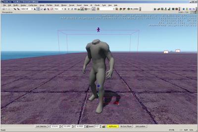
So now that you have the character in the engine, let’s check out the skeleton, to do this, go to the console (‘
~ ’ key) and type in ‘
p_draw_helpers 1 ’, without the ‘’ of course, and press enter. You should see something like this:

Character.chr with ‘ p_draw_helpers ’ enabled, this shows the physical hit mesh.
If the skeleton is in the default pose, you might need to toggle ‘ AI/Physics ’ in the lower right.
So now you can see the deforming skeleton, and you can jump into game and shoot/test it. But how do you know if the hit materials are set up properly? If you jump into game mode and press ‘ 7 ’, you will see that you have a weapon that tells you the material of any object you point at, and it will tell you even more info about that item if you ‘shoot’ it. Here is what it looks like when pointing at the hit skel:

Using this tool you can debug all the parts of your skeleton, checking them to see that they are set up with the proper materials.
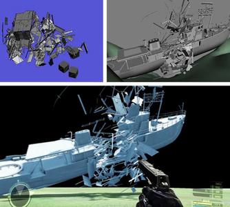
Ragdolls
Testing ragdolls in the engine can be a lot of fun, especially for non humanoids.
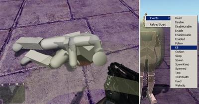
There are three ways to test the ragdoll physics of a character, the two best being shown above: Either gun them down, or right click them and select “ Events>Kill ”

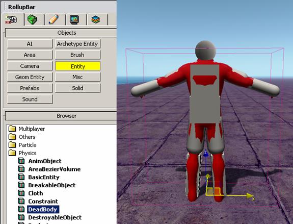
You can also add the character as a DeadBody entity. Be sure to uncheck ‘resting’, when you enter the game, or enable ai/physics, the ragdoll should simulate.
Special Note: I should say that ragdoll functionality has been been ‘nerfed’ in Crysis, and once a ragdoll rests it will cease to be simulated. (if your SDK is augmenting the commercial Crysis game) That said, licensees receive code drops with all CryENGINE®2 features intact.