|
Asset Creation Manual
|
   |
   |
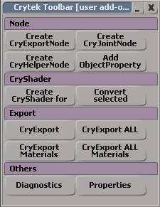
Using the SOFTIMAGE|XSI Exporter
|
Asset Creation Manual
|
|
|
Possible types of assets in an XSI scene:

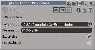
You can choose the type of asset, i.e. .cgf, .cga or .chr file (refer to CryExport for more details). Additionally you can choose whether this particular asset should be exported during when using the Export all command. Check merge, if the asset has no functionality and is composed of many separate geometry nodes. The exporter will automatically remove the hierarchy and compress the data for the target asset. The values are stored in custom properties called ExportProperties . You can easily access them from the Explorer.
The joint needs to be placed between two geometry nodes, so that its bounding box is intersecting with the bounding box of the two objects it should keep together. The null has a text property in which you can adjust the physical parameters for the joint, i.e. limit=10000
Joint parameters:
CryObjectProperty settings
NOTE: Either use Mass or Density, not both together.
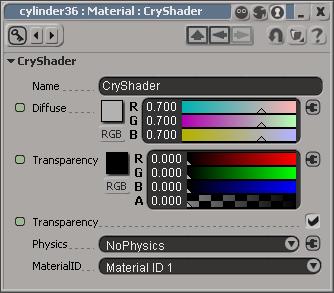
To assign a CryShader to an object, select it use Create CryShader for selections . This creates a new material without Physics settings (NoPhysics). If you want to assign cryshader to single polygons, you need to create a cluster before you can assign a new Cryshader to them.
Second you can select existing materials in the Explorer and use Convert selected materials to Cryshader . As the name suggest, selected materials are converted to the CryShader format.
The plugin automatically adds prefix numbers to the materials to keep the order of the materials consistent. CryENGINE®2 applies the materials in the order of the .mtl file this order will not change creating the .mtl file (CryENGINE®2 Material file).
If you convert an existing set of materials to the Cryshader, make sure there are no other unused Cryshader materials in the same library. This would interfere with the numbering process. Collect all materials of one asset in a Material library and rename it. The name will be used to create an mtl file, or to connect the asset with an existing .mtl.
Physics Parameters:
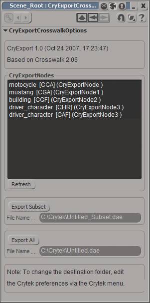
All the asset and their corresponding Crytek compiler out filename and file type are listed in the CryExportNodes list. If you want to export only some assets of the scene, you can select the assets in the list and use Export Subset . The specified “_Subset.dae” COLLADA file will be exported.
Export All creates a COLLADA file with the name you specify, containing all the assets from the scene. The RC will then create separate files in the target format.
The CryExport exporter takes into account every asset individual property and will only export the required elements for that particular asset/file type in the intermediate COLLADA file.
You can also access a shortcut to the Export All function through the Crytek Menu. This save some time during the testing and learning phase.
Here’s what gets exported for the possible file types:
CGF : Triangulated mesh geometry, hierarchy, material and image
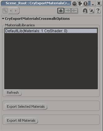
You can choose between exporting the selected materials in the list or exporting all the materials at once.
You also have a shortcut to create a material file for all the available Material libraries.
Here’s what gets exported for the possible file types:
MTL : material file, taking into account the diffuse colours and texture paths. They will be created relative to the Game folder.
The properties are saved in the XSICryExport preferences. (/XSICryExport.xsipref)
You can check them with various console commands:
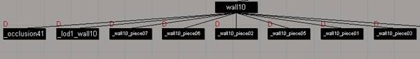
Pieces for breakable objects Pieces geometry nodes can be placed anywhere in the hierarchy. They can be named to your liking, but need an underscore as the first character. i.e. _piece01, _wall01_part01, _blah
Branches The branches nulls are needed for the setup of bending vegetation leafs. The nulls are used as joint in the engine, through which the physics engine interpolates a rope spline, with which the player can interact. The branches have a special and strict naming convention: branch<#>_<#> i.e branch01_01, branch01_02, branch02_01, branch02_02, branch02_03
The system is unconventional, but very efficient. The bounding boxes of the branch nulls needs to enclose vertices which are influenced by the spline. Ideally you choose the vertices lying in the center line of a branch (it works especially well for trees with large leafs, like palm trees). The engine then makes a lookup in the UV coordinates and checks for all vertices, which have connected UVs. All the connected vertices are taken into account when the physics calculates the deformation. The cool thing about it is, that you do not need to create weighting on the vertices and you only need to set up one (!) leaf and all other instances in the asset will automatically work, if they share the same UV coordinates. You can even deform the other leaves and still have the effect applied.
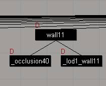
LODs You can make use of the Level of detail functionality of CryENGINE® 2 by linking the LODs to the Base object, add an UNDERSCORE to the name and number themaccordingly. The rule of thumb is to reduce the polycount for every LOD step by 50%. If you only remove 20% of the polygons, the LOD will not load for being insufficient. There is a exception, though. If you use less different materials than on the previous LOD level, the LOD will still work, even if there are not 50% of the polygons saved.
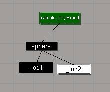
You can also add a postfix with the name of the LOD0 (in this case “sphere”) to the name of the LODs, i.e. _lod1_sphere or _lod2_justforfun. Important are only the first 5 characters.